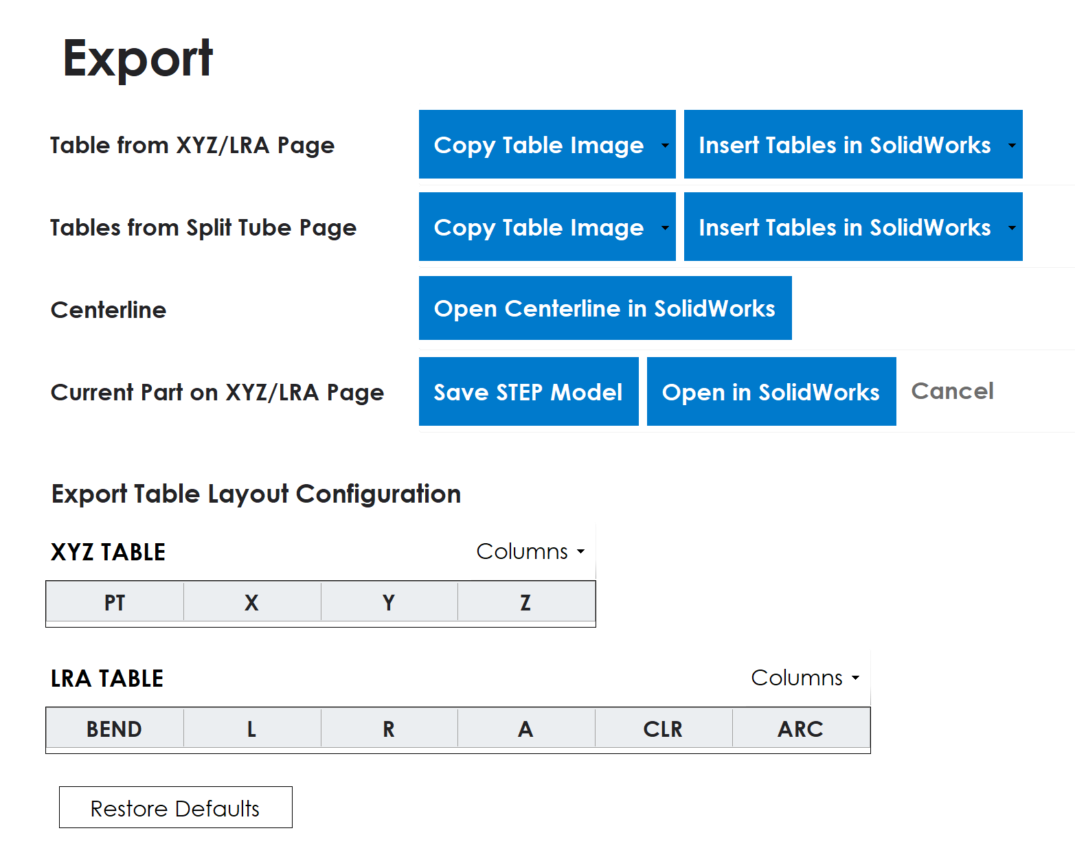
Bring your BS Tube work into drawings, centerline sketches, and solid models. Four export groups keep the original part, split-tube tables, and SolidWorks outputs together in one place.
Table from XYZ/LRA Page
Export the current part's XYZ coordinates, LRA bend data, or both tables together.
Copy Table Image
Copy the complete table image to the Windows clipboard, ready to paste into a drawing, document, or email.
Insert Tables in SolidWorks
Add editable native tables to the active SolidWorks drawing, rather than a picture of the data.
Table values retain the units selected in BS Tube; they are not converted to the drawing's units.
Tables from Split Tube Page
Export a piece's local XYZ coordinates or displayed LRA values after splitting a tube. Choose a numbered table, such as XYZ Table 1 or LRA Table 2, from either the image or drawing menu.
Only populated pieces appear, up to Tube 4. Each exported table includes its tube number in the title, so separate sections remain easy to identify. These exports use the Split Tube data, not the original unsplit part's tables.
Centerline
Open the current XYZ/LRA part's real 3D centerline in a new SolidWorks part.
Open Centerline in SolidWorks
Create the same fully defined native 3D path used by the solid-part export: tangent straight lines and bend arcs, driving CLR dimensions, and fixed original XYZ reference points. Only the centerline is created, with no stock profile or sweep and no sketch-type dropdown.
SolidWorks must be running with a valid default Part template. No blank part needs to be opened first, and stock dimensions are not required. Existing documents are left untouched. The new part is left open and unsaved; save it as SLDPRT to keep the editable centerline.
Current Part on XYZ/LRA Page
Create a solid model from the current path and stock profile, including bend CLR, OD or width and height, wall thickness, and corner radius where applicable. Round, square, and rectangular tubes and bars are supported.
Save STEP Model
Save the solid geometry as a STEP file for use in compatible CAD software.
Open in SolidWorks
Create a new editable native part with a fully defined 3D centerline, dimensioned profile sketch, and sweep. SolidWorks must be running with a valid default Part template. The new part is left open and unsaved; save it as SLDPRT to keep the editable features.
Filenames use the Part number from XYZ/LRA, or BS Tube Model when it is blank. The generated stock has a constant section and square-cut ends. It does not reproduce imported holes, slots, or formed ends; Unbend Model handles supported source-model feature preservation.
Customize your tables
Choose the columns, order, and precision that suit your drawing or report. The same layout settings apply to XYZ/LRA and Split Tube exports, for both copied images and SolidWorks drawing tables.
Show or hide columns and move them left or right.
Set numeric columns to 0-4 decimal places. PT and BEND remain whole-number identifiers.
Add the optional XYZ CLR column for each point's centerline radius.
Add the optional LRA DIR column: RH for right-hand bends, LH for left-hand bends. Straight rows stay blank.
CLR in XYZ and DIR in LRA are off by default. The configuration area shows headings only; exported tables still include all data rows. Layout choices are remembered, Restore Defaults resets them, and display precision never changes the underlying geometry.